How to Calibrate Load-Cell Weighing Systems for Cement Silos: An Automation Engineer's Blueprint
Metrological Overview & Calibration Drift Physics
In continuous or batch-type ready-mix concrete production, mass-measurement precision dictates final structural performance and specification compliance. The cement scale hopper weighing system—typically suspended beneath the cement silo screw conveyor discharge butterflies via a three-point or four-point strain-gauge load cell matrix—is subject to intense mechanical fatigue, erratic dynamic torque loops, and severe environmental vibration vectors.
Calibration drift within these sensors does not merely cause minor recipe variances; it skews the strict water-to-cement ratio (w/c), degrades compressive strength characteristics, causes raw material loss, and violates structural compliance parameters (such as EN 206 or ASTM C94 tolerances).
This calibration manual provides industrial automation technicians, plant electricians, and site managers with the exact physical alignment steps, digital signal transducer millivolt (mV/V) balancing protocols, and PLC calibration configurations required to eliminate weighing errors and stabilize the plant's batching loop.
The 3 Root Causes of Load-Cell Measurement Inaccuracy
Before executing a digital calibration sweep at the primary PLC automation terminal, field technicians must isolate and neutralize mechanical interference variables that trigger signal hysteresis.
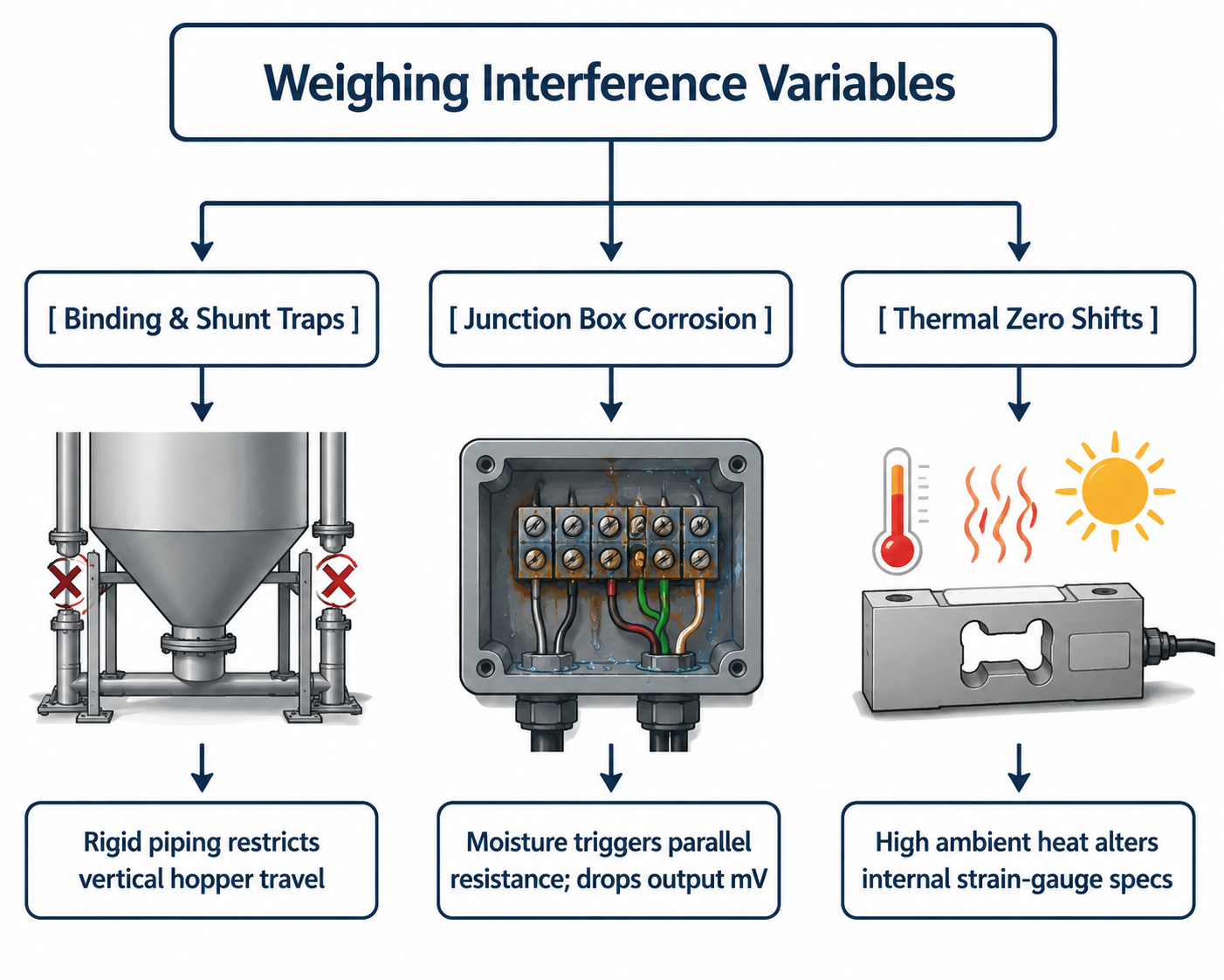
1. Mechanical Binding and Structural Shunting
A load cell operates on microscopic structural deflection. If the flexible canvas or neoprene drop chutes between the screw conveyor discharge head and the scale hopper become packed with hydrated crust, they harden into a mechanical shunt. This structural binding absorbs a percentage of the material weight, preventing gravity from transferring the true downward vertical force vector to the load cell sensors.
2. Junction Box Signal Imbalance (Summing Errors)
Because multiple load cells are wired into a single central junction box, their millivolt outputs must be perfectly balanced. If moisture, airborne carbon dust, or fine cement micro-particles penetrate the junction box housing (violating its IP67 rating), a parallel resistance path is created across the terminal blocks. This drops the return signal voltage, causing the central A/D (Analog-to-Digital) converter card to read incorrect weight profiles despite perfect sensor hardware.
3. Excitation Voltage Volatility and Thermal Zero Drift
Industrial load cells require a highly stable, non-fluctuating excitation voltage (typically 5V DC or 10V DC) from the automated weight indicator or PLC module. If the plant's 24V/10V DC power supply loops experience cyclic interference from massive 45kW twin-shaft mixer motor line surges, the input reference voltage shifts. This forces an artificial drift in the sensor's raw zero-balance point.
Technical Calibration Specifications & System Tolerances
The metrological specification matrix below outlines the strict physical boundaries and electronic parameters required to maintain optimal digital batching scale precision.
| Operational Parameter / Metric | Target Engineering Boundary | Emergency Fault / Failure Threshold | Specialized Measurement Device |
|---|---|---|---|
| B2B Weighing Error Limit | ≤ ±1.0% of Total Scale Span | > ±2.0% (Recipe Non-Compliance) | Certified Standard Test Weights |
| Sensor Zero-Balance Signal | 0.0 mV to ±0.05 mV / Volt | > ±0.1 mV/V (Zero Point Drift) | 4.5-Digit True-RMS Multimeter |
| Insulation Resistance | ≥ 5000 MΩ at 50V DC | < 1000 MΩ (Internal Moisture Fault) | Insulation Megohmmeter |
| Excitation Stability Limit | 10.00 V DC (Stable Loop) | < 9.75 V DC (Excitation Dropout) | Low-Noise Digital Volt Meter |
| A/D Conversion Resolution | Minimum 24-Bit Architecture | < 16-Bit (Inaccurate Scale Steps) | Industrial Automation Dashboard |
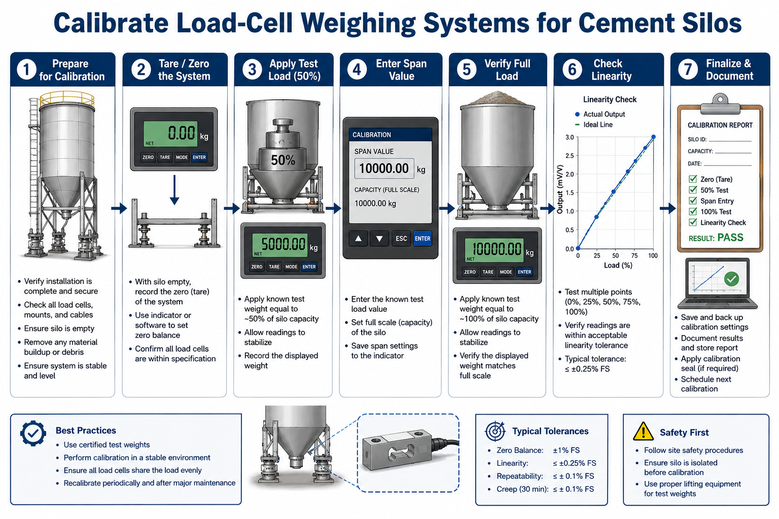
Step-by-Step Comprehensive Calibration Procedure
To guarantee full legal metrological certification, engineers must execute a structured Three-Point Calibration Loop utilizing physical, certified dead-weights. Dummy electronic calibration (e-cal) schemes must only be utilized for temporary troubleshooting runs.
Step 1: Execute Complete Mechanical Isolation & Zero Balancing
- Isolate the batching tower power grid via standard Lockout-Tagout (LOTO) protocols.
- Inspect the scale hopper body. Verify that all anti-tip check rods maintain a minimum clearance gap of 1.5 mm to 2.0 mm and are completely free of binding.
- Clean all canvas drop sleeves. Ensure the hopper can travel vertically without restriction.
- Power up the PLC control desk. Let the electronic weighing indicator warm up for 20 minutes to eliminate thermal variable drift.
- Navigate to the calibration terminal screen and execute the Dead-Zero (Tare) Capture Command. The system will record the raw millivolt footprint of the empty hopper container as
0.00 kg.
Step 2: Perform the Mid-Span Span-Load Injection Test
- Securely suspend certified test weights onto the structural hanger tabs engineered onto the sides of the cement scale frame.
- The initial calibration mass injection must represent at least 30% to 50% of the total scale capacity (e.g., for a 1,000kg capacity cement scale, inject a minimum of 400kg of certified weights).
- Wait 10 seconds for dynamic vibration vectors to settle.
- Compare the physical weight totals with the digital numeric display on your automation screen.
- If a deviation exists, enter the precise numeric value of the physical weights into the PLC’s Span Calibration Register Input and press enter to calibrate the sensor's electronic slope factor.
Step 3: Verify Linearity and Hysteresis Variance
- Gradually add the remaining test weights up to 100% of maximum scale capacity in equal increments (e.g., checking at 200kg, 400kg, 600kg, 800kg, and 1,000kg intervals).
- Record the digital output values during the loading cycle.
- Gradually remove the test weights in reverse order, logging the tracking readouts to verify the system's hysteresis curve.
- If the display errors at the midpoints exceed ±1%, the sensors are experiencing nonlinear structural deflection. Check for cross-loading forces or replace the old load cell sensors entirely.

Automation Maintenance & Corner Adjustments Checklist
If you find that one corner of your three-point or four-point cement scale registers a different weight than the other corners when an individual test weight is moved around, the system requires a Corner Adjustment (Potentiometer Balancing) inside the junction box:
- Locate the Summing Board: Open the IP65 junction box casing. You will locate an array of miniature variable screw resistors called trimming potentiometers (Trimpots), with one assigned to each distinct load cell terminal channel.
- Balance the Corner Readouts: Place a single 100kg test weight directly above Load Cell 1. Record the weight. Move that exact weight above Load Cell 2.
- Execute Micro-Trimming: If Cell 2 registers
98kgwhile Cell 1 registers100kg, use an insulated precision screwdriver to gently turn the trimpot screw assigned to Cell 2 until its display tracking balances to match Cell 1 perfectly. Repeat this procedure across all sensor channels until corner errors are squashed below 0.1% variance thresholds