Preventing Cement Screw Conveyor Caking in High-Humidity Tropical Construction Sites
Thermodynamic Mechanics of Cement Caking
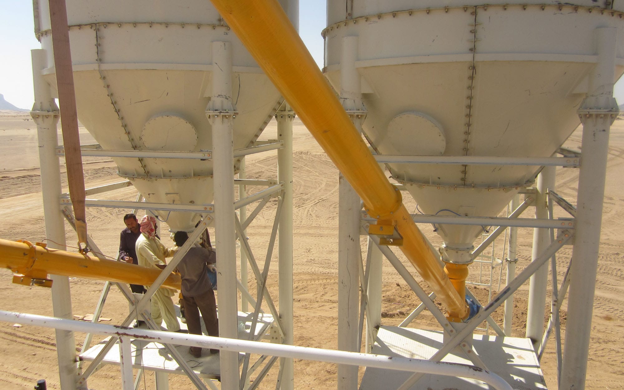
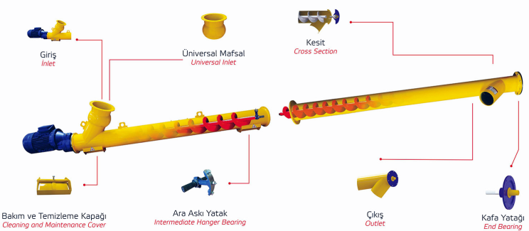
In tropical or coastal infrastructure development sectors (e.g., coastal Philippines, equatorial Indonesia, or the Arabian Gulf), concrete batching plant operators face severe efficiency losses due to material binding within bulk powder delivery loops. The screw conveyor (augur fly flyways)—responsible for transporting fine dry Portland cement from the lower discharge butterfly valves of the bolted silos up into the dynamic central cement scale hoppers—is highly susceptible to moisture ingress.
Cement caking is not merely a mechanical blockage; it is a rapid chemical hydration process. Dry cement powder possesses an extreme thermodynamic affinity for ambient moisture. When air with a relative humidity exceeding 75% penetrates the screw housing, the surface particles of calcium silicate undergo localized flash-hydration, curing directly onto the cold metallurgic skin of the internal mechanical assembly.
This technical diagnostic guide isolates the thermodynamic factors behind material caking, outlines mechanical inspection tolerances, and delivers actionable preventive maintenance protocols to secure uninterrupted bulk feeding sequences.
The 3 Critical Structural Ingress Vectors
To design an effective anti-caking strategy, field installation engineers must understand exactly how atmospheric moisture breaches a pressurized bulk powder conveyor line.
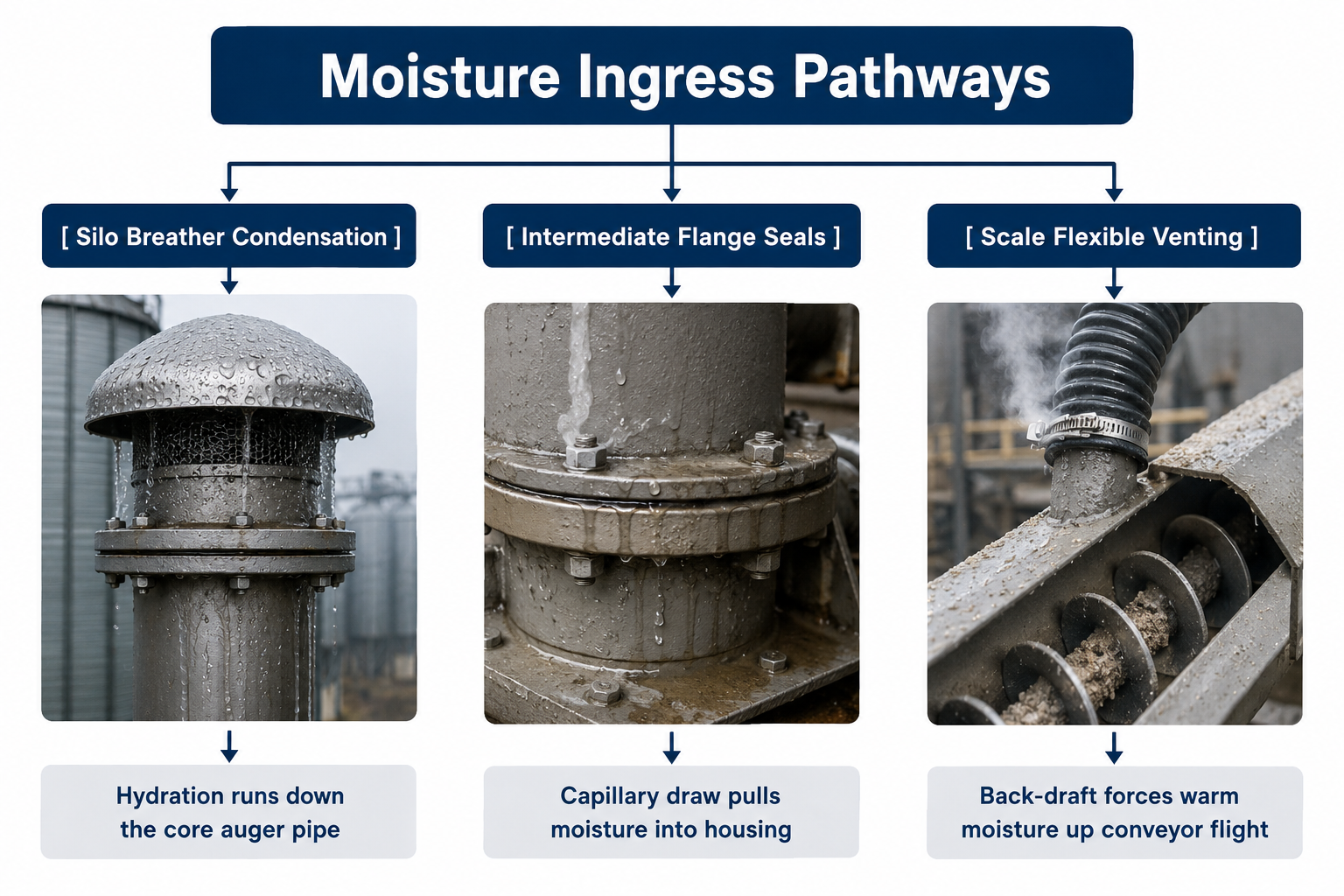
1. The Intermediate Flange and Hanger Bearing Seals
Standard industrial screw conveyors (such as standard WAM series or tier-1 Chinese configurations) are fabricated in modular 3-meter or 4-meter pipe segments bolted together via exterior structural flanges.
- Capillary Draw: If standard asbestos or low-grade rubber gaskets are used, cyclic vibration torque vectors from the main 11kW to 30kW drive motors will cause subtle bolt relaxation. The resulting microscopic flange micro-gaps allow highly humid tropical ambient air to be pulled straight into the moving material flow via capillary suction forces.
- Hanger Bearing Obstructions: Intermediate hanger bearings inside the conveyor pipe restrict localized flow. Material slows down at these points; if moisture is present, cement cakes directly around the bearing block, leading to high-load motor trips.
2. Silo Top Venting Condensation Cascades
When bulk pneumatic tankers pump dry cement into storage silos at high velocities, air pressure inside the silo skyrockets.
- The Thermal Inversion Trap: At night, as ambient coastal temperatures drop rapidly, the warm, trapped air inside the steel silo shell condenses on the upper internal roof plates. This liquid water runs down the interior walls, collects at the lower discharge cone, and enters the screw conveyor inlet throat as a highly concentrated fluid slurry during the initial morning batching sequence.
3. Scale Hopper Back-Draft Dynamics
The exit nozzle of the screw conveyor drops material straight into the closed cement scale hopper.
- Piston Pumping Effect: As heavy concrete mixers wash out beneath the tower or dump fresh wet batches into transit mixers, high-temperature, high-humidity steam rises directly up through the batching tower framework. As the cement scale hopper fills and empties, it behaves like a pneumatic piston, forcing this hot, humid air up the discharge chute of the screw conveyor, caking the final flight sections.
Structural Specifications & Operating Fluid Boundaries
The specification matrix below outlines the strict physical parameters required to stabilize a bulk powder conveyor loop under high relative humidity stress environments.
| Mechanical Assembly Node | Optimal Engineering Metric | Material Failure / Caking Threshold | Precision Measurement Device |
|---|---|---|---|
| Auger Flight Incline Angle | 20° to 35° (Optimal Throughput) | > 45° (High Back-slip / Compression Friction) | Digital Inclinometer Gauge |
| Screw Core Shaft Runout | ≤ 2.0 mm total indicator reading | > 5.0 mm (Localized Compaction Heat) | Magnetic Base Dial Indicator |
| Silo Top Air Pressure | 0.02 MPa to 0.05 MPa (Safe Venting) | > 0.10 MPa (Moisture Condensation Push) | Differential Pressure Sensor |
| Drive Gearbox Temp Profile | 45°C to 65°C standard duty | > 85°C (Bearing Seizure Risk) | Infrared Thermal Laser |
| Ambient Relative Humidity | < 60% (Optimal Powder Handling) | > 75% (Mandatory Anti-Caking Protocols) | Digital Psychrometer |
Step-by-Step Preventive Engineering Action Plan
To completely isolate your bulk material delivery loops from caking-induced mechanical lockups, implement these engineering modifications across your plant layout:
Step 1: Replace Flange Seals with High-Density Polyurethane Gaskets
Dismantle all modular conveyor pipe segment flanges. Scrape off the factory-standard paper or asbestos gaskets. Apply a continuous bead of high-temperature RTV silicone sealant alongside a custom-cut, heavy-duty 3mm High-Density Polyurethane (HDPE) or Viton gasket strip. Torque all structural flange bolts utilizing a cross-pattern locking sequence to 120 Nm to eliminate vibration-induced shifting.
Step 2: Implement a Pneumatic Anti-Caking Air Purge
Install an automated fluidization and dry air injection loop at the lower collection throat of the conveyor. Connect a line from a dedicated air dryer block (delivering pure dry air at 0.4 MPa) straight into three fluidization nozzles tapped at 120-degree intervals around the intake pipe.
- Automation Configuration: Program the central Siemens/Omron PLC to fire a brief 3-second dry air blast right before the main conveyor motor starts spinning, breaking up any overnight localized packed crust.
Step 3: Enclose and Vent the Scale Drop Chute
Replace standard loose canvas or non-breathable rubber flexible drop drops between the conveyor discharge head and the cement scale hopper. Install a high-durability anti-static, waterproof canvas sleeve (such as Nomex or Neoprene-coated nylon fabric). Install a dedicated, miniature mechanical air venting valve on top of the scale hopper to vent displaced air sideways away from the conveyor mouth, neutralizing the back-draft moisture pump completely.
Part 2: Scene-Specific Anti-Caking Solutions
Environmental topography dictates mechanical wear. Sourcing agents must adjust additional defensive measures based on the physical staging layout of the batching infrastructure.
1. Open-air Temporary Construction Sites
- Additional Measures: Open-air yards in tropical monsoon zones are subject to sudden torrential downpours. Contractors must install a rigid, heavy-duty sunshade and rainproof steel canopy directly above the entire length of the screw conveyor. The canopy roof must feature a strict 30° inclined drainage slope to guarantee zero rainwater accumulation. Additionally, install a bolt-on, replaceable moisture-absorbing silica gel box at both the conveyor inlet throat and the outlet chute, with a mandatory maintenance replacement cycle every 7 days.
- Scene-Specific Advantage: The physical canopy completely eliminates direct contact between raw cement steel components and external rainwater, while the inline silica gel boxes aggressively extract localized ambient moisture from the surrounding intake air currents, maintaining a safe humidity barrier around the conveyor joints.
2. Indoor Factory Workshops
- Additional Measures: For enclosed precast factories and concrete block workshops, hard-wire the screw conveyor’s air intake ports directly into the building's centralized dehumidification system, holding the internal relative humidity of the shop floor at a strict 40% to 50% range. Concurrently, mount digital temperature sensors onto the exterior conveyor pipe shell. If internal material friction or ambient heat drives the shell temperature above 35°C, the PLC automation desk must automatically trigger an external water-spray mist cooling system over the pipe exterior.
- Scene-Specific Advantage: The centralized HVAC dehumidification integration delivers an uncompromised, stable dry-air environment year-round, while the active shell cooling system counteracts high-temperature heat buildup, stopping hot tropical ambient spikes from accelerating the cement's molecular hydration timeline inside the tube.
3. Underground Construction Sites (Tunnels & Mining)
- Additional Measures: Underground shafts present extreme ambient humidity, seepage water, and strict explosion-hazard ratings. Engineering teams must deploy specialized explosion-proof dehumidifiers outfitted with integrated automated drainage pumps. Install a high-visibility digital water level alarm inside the dehumidifier's drainage collection tank; when liquid levels breach the warning threshold, the system flags the maintenance crew for immediate manual drainage. Furthermore, install a heavy-duty flexible expansion joint at the interface connecting the conveyor to the underground delivery pipeline.
- Scene-Specific Advantage: The certified explosion-proof rating satisfies strict mine and tunnel ventilation safety criteria, while the heavy flexible expansion joints accommodate structural stress deformations caused by ground subsidence, shifting loads, or blasting vibrations, ensuring a stable, leak-proof material flow.