Self-Loading Concrete Mixer Truck Operation & Fluid Diagnostics Guide
An expert engineering operation manual detailing self-loading concrete mixer parameters, pre-start checks, loading sequences, and hydraulic diagnostics.
Metrological Overview & Hydraulic Engineering Dynamics
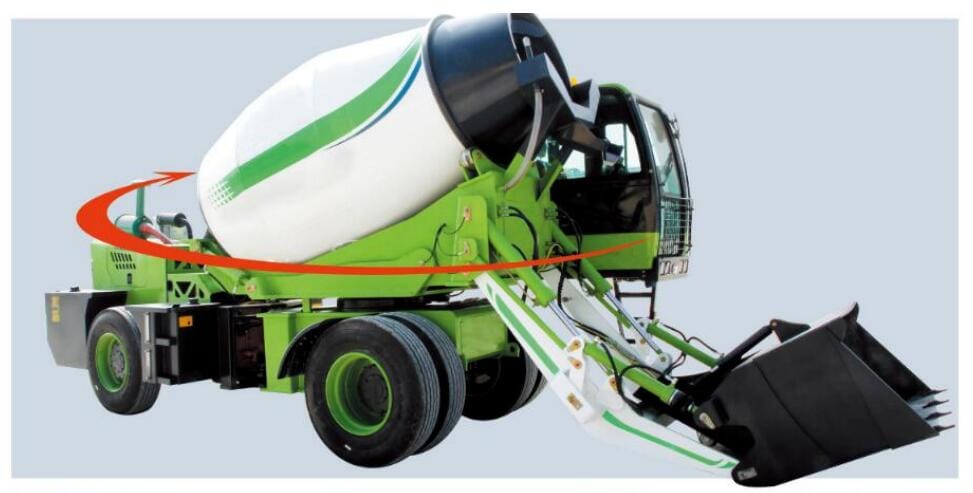
In remote infrastructure development sectors, rugged terrain construction zones, and utility expansion pathways where centralized ready-mix batching towers are unavailable, the self-loading concrete mixer truck functions as an all-in-one concrete manufacturing facility. This mobile unit integrates an automated aggregate bucket loader, a dynamic onboard electronic weighing scale system, a vertical-swing mixing drum, and a cross-border all-wheel-drive transport chassis into a single cohesive system.
Operating under continuous shock loads and abrasive dust environments, the machine's mixing drum and lifting arm kinematics rely entirely on a stable, high-pressure hydraulic fluid distribution circuit.
aintaining the equipment within rigid operating parameters is non-negotiable for site managers. Deviations from factory-calibrated system pressures or failure to enforce strict material charging sequences introduce critical fluid boundary failure loops.
These errors lead to hydraulic pump cavitation, premature wear of the manganese steel drum liners, severe concrete material segregation, and irreversible concrete hydration blockages inside the mixing drum cylinder.
This technical operation and troubleshooting manual establishes standard metrological working parameters, defines pre-start fluid thresholds, and provides structured diagnostic sequences to optimize machine lifecycles.
Technical Operation & Fluid Calibration Manual
1. Primary Equipment Working Parameters
To prevent drivetrain strain and hydraulic component degradation, operators must strictly regulate the heavy machinery within these standard operating limits:
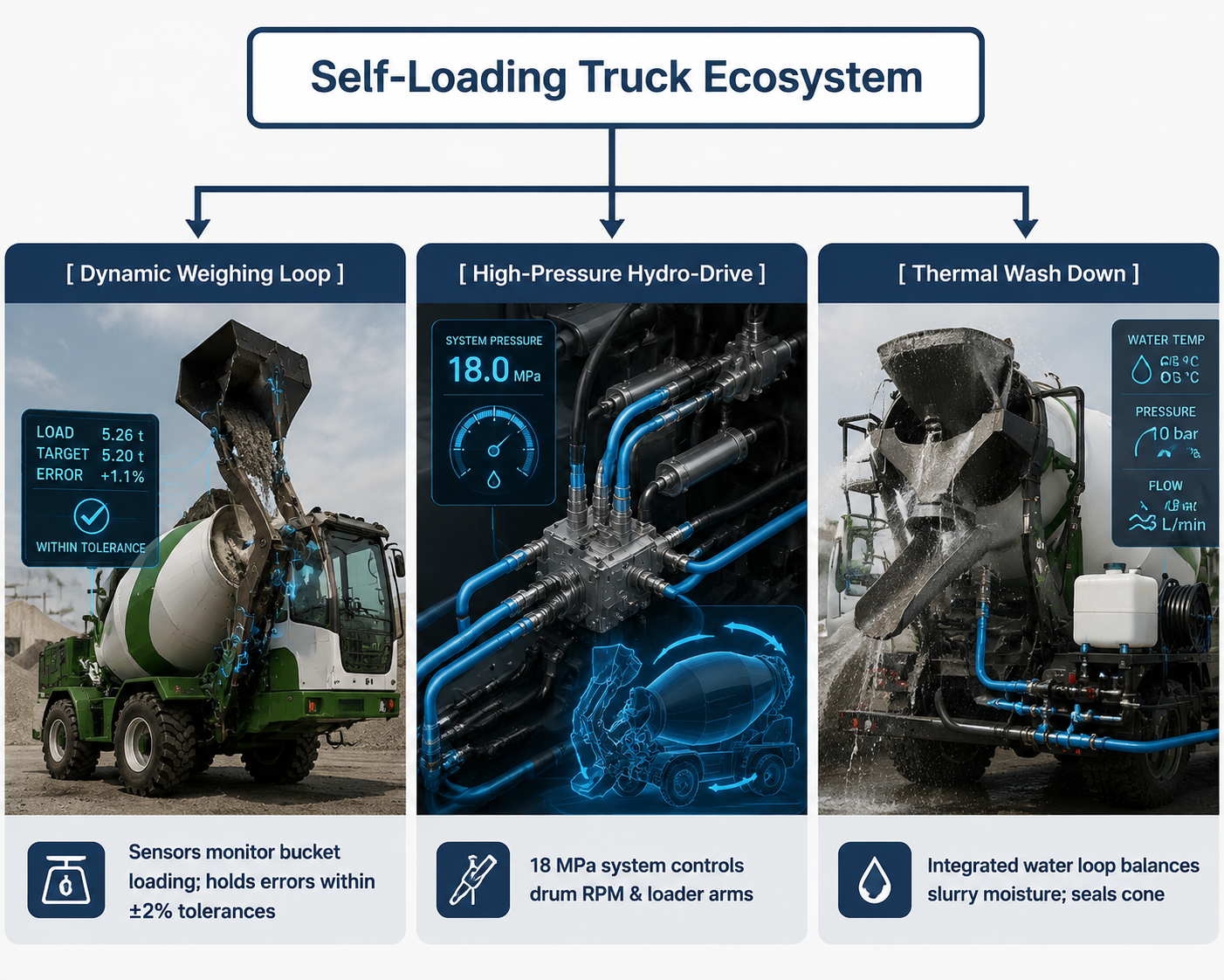
- System Hydraulic Pressure: 16.0 MPa to 18.0 MPa (160–180 bar). Warning: Operating continuously past 20.0 MPa triggers rapid relief-valve seal erosion.
- Mixing Mode Drum Speed: 12 to 18 RPM (Revolutions Per Minute).
- Volumetric Output Envelope: 1.2 m³ to 6.5 m³ of certified concrete slurry per batch.
- Maximum Site Travel Speed: ≤ 40 km/h. (When traveling loaded over rough off-road job sites, speed must be restricted below 5 km/h to prevent geometric center-of-gravity tip-overs).
2. Pre-Start Fluid & Mechanical Inspection Protocol
Before turning the diesel ignition switch, field technicians must execute this multi-point verification checklist:
- Diesel Fuel Sub-System Reserves: Ensure fuel tank levels indicate ≥ 70% capacity to prevent fuel line air-starvation loops when climbing steep quarry slopes.
- Hydraulic Fluid Reservoir Monitoring: Inspect the clear sight-glass gauge on the hydraulic oil tank. The oil level must align precisely with the mid-level indicator line.
- Cooling System Volumes: The primary diesel radiator and hydraulic fluid fan heat-exchanger water cooling tanks must be filled to 100% full capacity.
- Pneumatic Tire Pressure Profile: Calibrate and match all heavy-duty off-road tires to a rigid boundary of 0.35 MPa to 0.45 MPa (3.5–4.5 bar).
- Structural Mechanical Fastener Torques: Use a calibrated click-type torque wrench to verify that all primary wheel hub bolts and drum support ring fasteners are torqued to ≥ 300 N·m. Inspect all high-pressure flexible hoses for visible pinhole weeping or cylinder rod scoring.
3. Engine Ignition & Power Take-Off (PTO) Engagement Sequence
- Step into the operator cab, verify that all hydraulic joystick controllers are centered in their neutral positions, and turn the ignition switch.
- Let the diesel engine idle smoothly for 3 to 5 minutes. This allows the oil pumps to distribute warm lubricating fluid evenly across the turbocharger bearings and engine block.
- Observe the dashboard analog pressure indicators. Verify that the primary hydraulic system pressure rises and stabilizes within the 16.0 MPa to 18.0 MPa operational band.
- Engage the clutch pedal completely, then actuate the switch to engage the Power Take-Off (PTO) drive shaft system to send fluid power directly to the main mixing drum gear transmission.
4. Automated Bucket Loading Sequence & Recipe Precision
To maximize blending homogeneity and prevent raw material clumping at the back of the mixing drum, operators must load raw aggregates through the hydraulic bucket system using this strict recipe sequence:
[ 1. Coarse Gravel ] ──> [ 2. Fine Quartz Sand ] ──> [ 3. Dry Portland Cement ] ──> [ 4. Metered Water Line ]
- Bucket Cycle Speed: The complete bucket lifting, scaling, and dumping arc must be regulated between 35 to 60 seconds per cycle to protect the cylinder valves from high-velocity shock loads.
- Electronic Scale Weighing Tolerances: The onboard digital scale system must run continuous dynamic algorithms to hold batching weight errors within these strict limits:
- Fine Sand Aggregate: ≤ ±2% Max Variance
- Coarse Stone/Gravel: ≤ ±3% Max Variance
- Metered Water Volume: ≤ ±1% Max Variance
5. Mixing, Transport, and Discharge Protocols
- Loading Rotation Speed: Keep the drum spinning at 8 to 12 RPM while the aggregate loader bucket is actively dumping material into the feed hopper.
- Active Mixing Execution: Once all dry components and fluids are inside the vessel, elevate the drum speed to 12 to 18 RPM for a minimum duration of 180 seconds to fully activate the concrete chemical hydration matrix.
- Transit/Transport Speed Limits: While moving the vehicle across the job site to the pouring location, drop the drum speed down to a slow 2 to 5 RPM. This keeps the slurry dynamic and prevents concrete segregation without generating excess heat in the hydraulic drive motors.
- Controlled Discharge Sequence: Align the vehicle with the pouring target, engage the hydraulic joystick to reverse the drum's rotation, and extend the directional discharge chute. Maintain the chute angle within a 25° to 45° slope to ensure an even, smooth concrete flow and prevent material separation.
6. Post-Operational Shutdown & Thermal Wash Down
Leaving residual concrete slurry inside the drum will destroy the mixing blades and freeze the gear drive system. Execute this wash down protocol immediately after completing the final pour:
- Inject 200L to 300L of clean water directly into the drum using the onboard high-pressure wash down pump system.
- Accelerate the drum rotation to maximum speed for 2 minutes. The water washes away aggregate dust and slurry caked onto the internal blades.
- Reverse the drum rotation to drain the dirty wash water completely out of the vessel.
- Return all hydraulic valves and control handles to neutral, let the engine idle for 2 minutes to stabilize temperatures, and shut down the engine.
Technical Specifications & Troubleshooting Tolerances
The industrial parameters matrix below outlines the strict physical dimensions, fluid boundaries, and calibration limits required to maintain optimal self-loading concrete mixer truck tracking.
| Operational Siting Node / Axis | Standard Engineering Target | Critical Failure / Fault Limit | Precision Diagnostics Device |
|---|---|---|---|
| Primary Main Loop Pressure | 16.0 MPa to 18.0 MPa | > 21.0 MPa (Relief Valve Blow-By) | Glycerin-Damped Oil Pressure Gauge |
| Pneumatic Tire Inflation | 0.35 MPa to 0.45 MPa | < 0.28 MPa (Asymmetric Load Drift) | Analog Calibrated Chuck Gauge |
| Onboard Water System Flow | 150 to 250 L/min | 0 L/min (Pump Air-Lock Seizure) | Digital Inline Turbine Flow Meter |
| Weighing Sensor Signal Voltage | 4-20 mA Analog Loop | Loop Disconnection (Signal Fault) | Digital True-RMS Multimeter |
| Drum Structural Wear Margin | Original Manganese Profile | ≤ 4.0mm Base Thickness (Liner Tear) | Ultrasonic Thickness Gauge |
FAQ
Q1: Why should an infrastructure procurement director mandate an all-wheel-drive (4x4) articulated chassis configuration over a rigid frame design for self-loading mixers?
A1: Sourcing directors must prioritize an articulated all-wheel-drive (4x4) chassis framework when finalizing heavy machinery procurement specifications for remote project sites. Rigid-frame mixer trucks experience tire slippage and high structural weld fatigue when navigating uneven, rutted quarry roads or muddy construction zones. An articulated chassis allows the front and rear frame sections to oscillate independently up to ±15° to 20° vertical slope variations. This design ensures that all four wheels maintain constant ground contact and tractive force, cutting drivetrain stress by 40% and preventing site-stuck accidents.
Q2: How does specifying an integrated electronic printing system on the hydraulic scale load cells benefit project management?
A2: Mandating an onboard thermal receipt printing network linked to the hydraulic scale load cells adds an essential layer of quality control for commercial construction operations. In remote regions where independent laboratory testing is unavailable, the mixer's automated printer generates a physical data receipt for every single batch. This receipt lists the exact weights of the sand, gravel, and cement loaded into the drum. This system provides clear proof that the concrete matches required engineering mix recipes, protects the project from structural product liability issues, and optimizes material tracking.
TAG
self loading concrete mixer,concrete mixer truck,self loading concrete mixer truck operation guide,how to operate a self loading concrete mixer,self loading mobile concrete mixer startup procedure,off road mobile concrete batching truck maintenance
Request Technical Blueprints & Factory Quotes
Submit your machinery parameters below. Connect directly with verified, certified heavy industrial manufacturers to receive custom foundation drawings, layout schematics, and direct-from-factory pricing.