Concrete Plant Pneumatic Loop Failures: Eliminating Solenoid Stiction & Butterfly Valve Air Locks
Pneumatic System Dynamics & System Risk Variables
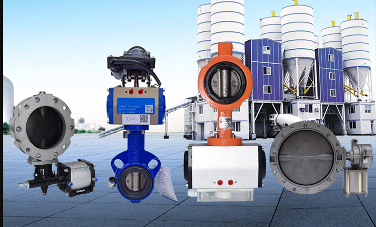
In fully automated ready-mix concrete production lines, the mechanical execution of software commands relies heavily on high-pressure fluid power. The central pneumatic distribution network controls the critical gate movements across the batching tower—including aggregate bin drop gates, cement silo discharge butterfly valves, water weigh-tank dump flaps, and the main twin-shaft mixer exit gate assembly.
Unlike heavy hydraulic rams used on massive mining platforms, pneumatic loops are favored in standard plants for their high cycle velocities, rapid actuation responses, and compressed footprints.
However, air systems are highly vulnerable to volatile environmental variables. When unconditioned, high-humidity ambient air interacts with abrasive industrial dust, it triggers internal line oxidation, lubrication washouts, and component failures.
A frozen aggregate gate or an air-locked cement butterfly valve stops production instantly, causing expensive material batch degradation and structural project line rejections.
This troubleshooting manual isolates the thermodynamic root causes of pneumatic loop failures, delivers precise bar/MPa operating thresholds, and provides a structured maintenance blueprint to resolve solenoid stiction and control loop drops.
The 3 Critical Pillars of Pneumatic Loop Failures
When a pneumatic actuator fails to stroke upon receiving a 24V DC signal from the main PLC automation desk, technicians must systematically evaluate the three failure vectors of fluid power.
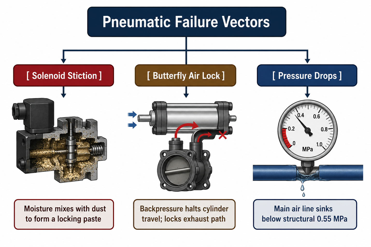
1. Solenoid Valve Stiction (Sticky Spool Syndrome)
Solenoid stiction occurs when the internal moving spool of a 5/2-way or 3/2-way directional control valve (commonly supplied by lineages like Festo, Airtac, or SMC) becomes physically stuck inside the valve body.
- The Emulsification Mechanism: If an inline air dryer fails, warm water vapor condenses inside the aluminum distribution manifold. This moisture washes away the factory-applied synthetic grease. The unlubricated surface mixes with migrating fine cement micro-particles, transforming into a dense adhesive paste that overpowers the magnetic flux of the 24V DC solenoid coil.
2. Butterfly Valve Air Locking & Backpressure Traps
Pneumatic butterfly valves used beneath cement and fly-ash scales require zero downstream exhaust restriction to complete their stroke.
- The Exhaust Restriction Block: When a valve fires rapidly, air must evacuate instantly from the opposite side of the cylinder piston. If the miniature sintered-bronze muffler silencers screwed into the exhaust ports of the solenoid manifold become clogged with caked cement dust, exhaust air is trapped. This builds backpressure inside the cylinder, locking the internal piston frame mid-stroke.
3. Dynamic Pressure Starvation
A standard plant compressor might show a safe pressure reading on the tank gauge while the plant is resting. However, when the aggregate doors, cement scales, and mixer gates all fire simultaneously within a tight 3-second automated cycle, the system experiences dynamic pressure drops. If the main air supply line drops below critical thresholds, the actuators lose their linear force output, leading to incomplete gate closures and raw material leakage.
Technical Specifications & Pneumatic System Tolerances
The fluid specification matrix below outlines the strict physical boundaries and pressure limits required to maintain optimal pneumatic system performance.
| Operational Node / Assembly | Optimal Metric Boundary | Emergency Failure Threshold | Precision Measurement Device |
|---|---|---|---|
| Main Loop Pressure Line | 0.65 to 0.75 MPa (6.5-7.5 bar) | < 0.55 MPa (Force Depletion) | Analog Glycerin-Damped Gauge |
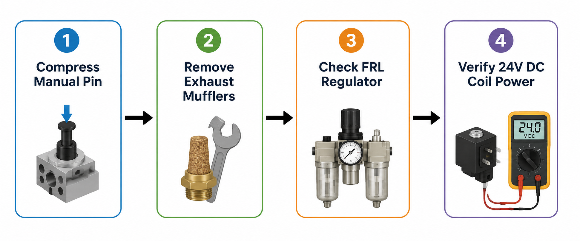
| Solenoid Coils Input Voltage | 24.0 V DC (Stable Supply) | < 21.0 V DC (Magnetic Drop) | True-RMS Digital Multimeter |
| Air Filtration Metric | 40-Micron Pre-filtering | Clogged Element (Air Starvation) | Differential Pressure Sensor |
| Lubricator Dropping Speed | 1 to 3 drops per 1,000L of air | 0 drops (Dry Cylinder Scuffing) | Visual Sight-Glass Dome |
| Air Line Moisture Dew Point | +3°C to +5°C (Refrigerated) | > 25°C (Water Condensation Trap) | Electronic Dew Point Meter |
Step-by-Step Emergency Diagnostic Checklist
If a critical scale or mixer gate freezes mid-batch, technicians must execute this structured fluid diagnostic loop to restore material flow before the concrete begins to set inside the mixing drum.
Step 1: Force a Mechanical Manual Override Test
Locate the specific directional control valve manifold corresponding to the failed actuator. Every premium industrial valve features a recessed, manual override button or pin. Use a 4mm pin punch or hex wrench to manually compress the override button.
- Diagnostic Inference: If the cylinder strokes smoothly under manual compression, your air supply, lines, and cylinder seals are healthy. The failure is completely electronic (blown 24V PLC relay card, severed wiring harness, or a fried solenoid coil). If the cylinder fails to move under manual compression, the failure is strictly fluid-mechanical (seized cylinder, caked material blockage, or zero air pressure).
Step 2: Clear the Exhaust Mufflers & Balance Backpressure
If the cylinder moves sluggishly or halts mid-stroke under manual override, locate the sintered-bronze mufflers on the solenoid exhaust ports. Unscrew the mufflers completely and cycle the valve again.
- Diagnostic Inference: If the cylinder strokes cleanly with the mufflers removed, the issue is an air lock due to blocked silencers. Soak the dirty bronze mufflers in a mild acid solution or industrial solvent for 15 minutes, blast them clean with high-pressure air, and reinstall them.
Step 3: Inspect the FRL (Filter-Regulator-Lubricator) Assembly
Head to the central plant air compressor node and check the inline FRL block:
- Drain the filter bowl manually to eject accumulated water pools.
- Check the oil level in the lubricator dome. If it is dry, refill it with specialized ISO VG 32 pneumatic tool oil.
- Adjust the lubricator drip needle valve until you can verify a consistent distribution of 1 to 2 micro-drops through the visual sight-glass during active batching cycles to lubricate the internal actuator seals.
If line pressure is verified at 0.7 MPa but the actuator still fails to stroke under load, internal piston seal blow-by has occurred. Disconnect the air line from the non-pressurized port of the cylinder and fire the valve. If air continuously streams out of the open port, the internal polyurethane piston U-cups have decayed. The cylinder must be unbolted and outfitted with an OEM seal rebuild kit immediately.