Preventing Aggregate Belt Conveyor Misalignment and Belt Slippage Accidents
Industrial Conveyor Dynamics & Operational Risks
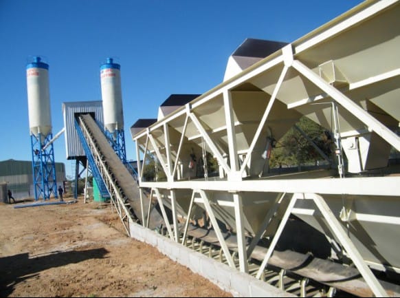
In high-output commercial concrete batching plants, the continuous transportation of heavy sand and coarse aggregate rely entirely on heavy-duty belt conveyor systems. On high-capacity belt-fed configurations (such as standard HZS120 or HZS180 lines), an inclined charging belt handles massive cyclic material volumes under brutal tension forces.
Because aggregate materials carry irregular moisture levels and abrasive dust, the mechanical belt tracking assembly operates under harsh conditions.
Conveyor belt misalignment (tracking drift) and belt slippage are not minor maintenance inconveniences; they are critical mechanical failures.
A drifting belt cuts its own edges against structural steel channel frames, causes massive aggregate spillage into the batching tower framework, accelerates motor gearbox thermal overloads, and triggers catastrophic friction-induced belt tracking accidents.
This engineering manual isolates the dynamic physics behind tracking drift and drive pulley slippage, delivers explicit mechanical alignment metrics, and provides a structured preventive maintenance protocol to protect your heavy industrial plant assets.
The 3 Critical Root Causes of Belt Misalignment & Slippage
To permanently resolve conveyor tracking faults, field technicians must look past superficial symptoms to diagnose the structural and environmental factors affecting belt tracking.
1. Structural Frame and Pulley Squareness Misalignment
A conveyor belt tracks toward the side that exerts the least tension force. If the head drive pulley shaft or the tail take-up pulley shaft drifts out of a perfect 90-degree square relative to the central longitudinal axis of the conveyor framework, tension vectors become uneven. The belt will immediately drift off-center toward the loose side, scraping structural steel channel lips and destroying the multi-ply EP (Ethylene Propylene) fabric edge cords within hours.
2. Pulley Lagging Wear and Friction Loss (Slippage Physics)
The heavy electric motor transfers torque to the rubber belt exclusively through the kinetic friction coefficient of the head pulley shell.
- The Wear Mechanism: Over multi-shift operations, the grooved (diamond-pattern) vulcanized rubber lagging on the drive pulley wears smooth or fills with fine sand slurry. When wet aggregates are introduced during tropical monsoons, a microscopic water film forms between the belt and the smooth steel or worn rubber pulley shell. The friction coefficient drops drastically, causing the drive drum to spin fruitlessly inside the belt loop, generating extreme localized friction heat that melts the internal rubber compounds.
3. Material Accumulation (Caking) on Return Idlers and Tail Pulleys
Fine sand particles and moisture form a highly dense, sticky slurry that passes beneath the primary and secondary polyurethane belt scrapers.
- The Profile Alteration Trap: This sticky aggregate paste bakes onto the surface of the return idlers and the shell of the tail pulley. As the caked material layer grows to a thickness of 5mm to 10mm, it alters the geometric diameter of the pulley unevenly. This forces the belt to continually climb the high spot of the debris crown, triggering violent, erratic tracking drift that cannot be resolved via standard take-up screw adjustments.
Technical Specifications & Conveyor Structural Tolerances
The mechanical tracking specification matrix below outlines the strict physical parameters and engineering tolerances required to stabilize an industrial aggregate belt conveyor system.
| Operational Parameter / Metric | Target Engineering Boundary | Emergency Failure / Accident Threshold | Specialized Measurement Device |
|---|---|---|---|
| Max Allowable Tracking Drift | ≤ ±40 mm from center axis | > 75 mm (Structural Steel Scrape) | Visual Alignment Laser / Ruler |
| Pulley Shaft Perpendicularity | ±0.5 mm across full shaft width | > 3.0 mm Deviation (Severe Drift) | Optical Total Station / Micrometer |
| Take-Up Screw Tension Balance | Equalized Newton/Meter Torque | > 15% Torque Imbalance across screws | Calibrated Industrial Torque Wrench |
| Drive Pulley Lagging Thickness | 10 mm to 15 mm Diamond Grooved | < 4 mm or Smooth (Imminent Slip) | Electronic Ultrasonic Thickness Gauge |
| Belt Speed Drop Slip Limit | < 2% deviation from nominal | > 10% (Triggers PLC Emergency Stop) | Digital Tachometer / Inductive Sensor |
Step-by-Step Conveyor Optimization & Realignment Protocol
When tracking failures occur on a primary 30-degree inclined aggregate charging belt, maintenance crews must execute this structured mechanical alignment sequence to restore system tracking.
Step 1: Execute Complete Mechanical Isolation & Zero Structural Cleaning
- Enforce strict Lockout-Tagout (LOTO) safety protocols on the primary conveyor motor drive cabinet.
- Manually scrape away all caked aggregate material and hardened cement-sand slurry from the face of the head pulley, tail pulley, snub rollers, and every individual troughing and return idler.
- Inspect and adjust the primary polyurethane H-type belt scraper. Ensure it exerts an even, continuous blade pressure (typically 1.5 to 2.0 bar) across the entire width of the belt to cleanly strip away moisture and fine sand slurry before it enters the tail assembly loop.
Step 2: Calibrate the Tail Pulley Take-Up Tension (The Squareness Loop)
- Loosen the structural locking nuts on both the left and right side tail take-up frames.
- Measure the exact spacing distance of the adjustment screws using digital calipers.
- Turn the tensioning screw on the side toward which the belt is drifting. Engineering Rule of Thumb: The belt always tracks toward the looser side; you must tighten the side it is drifting toward, or loosen the opposite side.
- Make adjustments in small, incremental 5mm steps. Run the conveyor empty for 5 full revolutions after each adjustment to allow the tension forces to equalize completely across the belt framework before tracking changes are measured.
Step 3: Implement Self-Aligning Troughing Idlers (Training the Belt)
If the conveyor frame has experienced structural warping due to severe ground subsidence or high thermal stress, manual screw adjustments are insufficient.
- Action: Install automated, pivot-mounted Self-Aligning (Training) Idlers at critical 15-meter intervals along the conveyor run, and one immediately preceding the tail pulley. When the belt drifts off-center, it contacts an integrated mechanical guide roller. This forces the entire idler frame to automatically pivot on its central axis, shifting the friction vector to push the belt directly back into the center line profile.
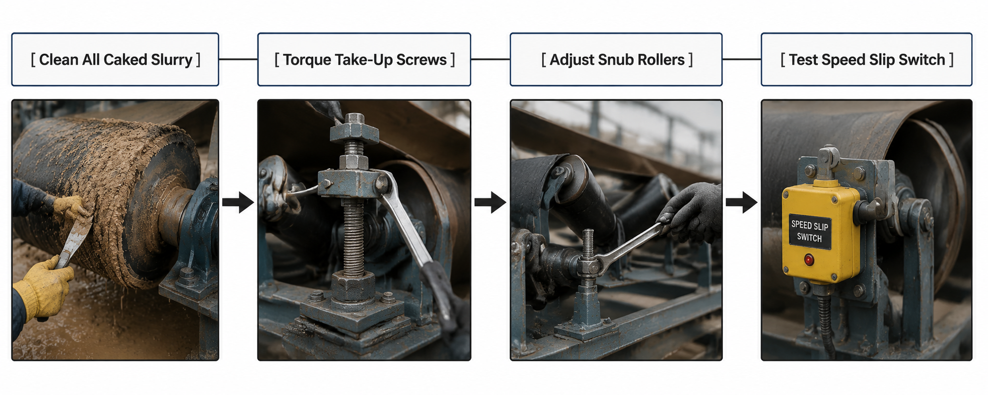
Step 4: Configure the Digital Slip Switch Automation Protection Loop
To prevent catastrophic fires caused by drive pulley friction heat during an aggregate slip event, install an inductive Conveyor Speed / Slip Switch Sensor on the non-driven tail pulley shaft or return belt face.
- PLC Automation Programming: Wire the sensor pulse line directly into your central industrial PLC card. Configure the software logic loop: If the primary motor contactor is engaged and running at full speed, but the tail pulley speed drops 10% below nominal RPM for more than 3 consecutive seconds, the PLC must execute an emergency motor trip sequence. This completely eliminates the possibility of belt melt accidents due to unmanaged drive pulley slippage.